
R0106-HP MSR Router Series Layer 3 - IP Routing Configuration Guide(V7)


19
The output shows that the BFD session has been created.
# Display static routes on Router A.
<RouterA> display ip routing-table protocol static
Summary Count : 1
Static Routing table Status : <Active>
Summary Count : 1
Destination/Mask Proto Pre Cost NextHop Interface
120.1.1.0/24 Static 60 0 12.1.1.2 GE2/1/1
Static Routing table Status : <Inactive>
Summary Count : 0
The output shows that Router A communicates with Router B through GigabitEthernet 2/1/1. Then the
link over GigabitEthernet 2/1/1 fails.
# Display static routes on Router A.
<RouterA> display ip routing-table protocol static
Summary Count : 1
Static Routing table Status : <Active>
Summary Count : 1
Destination/Mask Proto Pre Cost NextHop Interface
120.1.1.0/24 Static 65 0 10.1.1.100 GE2/1/2
Static Routing table Status : <Inactive>
Summary Count : 0
The output shows that Router A communicates with Router B through GigabitEthernet 2/1/2.
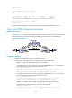
BFD for static routes configuration example (indirect next hop)
Network requirements
As shown in Figure 4:
• Router A has a route to interface Loopback 1 (2.2.2.9/32) on Router B, with the output interface
GigabitEthernet 2/1/1.
• Router B has a route to interface Loopback 1 (1.1.1.9/32) on Router A, with the output interface
GigabitEthernet 2/1/1.
• Router D has a route to 1.1.1.9/32, with the output interface GigabitEthernet 2/1/1, and a route to
2.2.2.9/32, with the output interface GigabitEthernet 2/1/2.
Configure the following:
• Configure a static route to subnet 120.1.1.0/24 on Router A.
• Configure a static route to subnet 121.1.1.0/24 on Router B.
• Enable BFD for both routes.