
R0106-HP MSR Router Series Layer 3 - IP Routing Configuration Guide(V7)


20
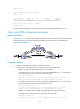
• Configure a static route to subnet 120.1.1.0/24 and a static route to subnet 121.1.1.0/24 on both
Router C and Router D.
When the link between Router A and Router B through Router D fails, BFD can detect the failure
immediately and inform Router A and Router B to communicate through Router C.
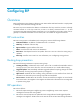
Figure 4 Network diagram
Table 5 Interface and IP address assignment
Device Interface
IP
address
Router A GigabitEthernet 2/1/1 12.1.1.1/24
Router A GigabitEthernet 2/1/2 10.1.1.102/24
Router A Loopback 1 1.1.1.9/32
Router B GigabitEthernet 2/1/1 11.1.1.2/24
Router B GigabitEthernet 2/1/2 13.1.1.2/24
Router B Loopback 1 2.2.2.9/32
Router C GigabitEthernet 2/1/1 10.1.1.100/24
Router C GigabitEthernet 2/1/2 13.1.1.2/24
Router D GigabitEthernet 2/1/1 12.1.1.2/24
Router D GigabitEthernet 2/1/2 11.1.1.2/24
Configuration procedure
1. Configure IP addresses for interfaces. (Details not shown.)
2. Configure static routes and BFD:
# Configure static routes on Router A and enable BFD control mode for the static route that
traverses Router D.
<RouterA> system-view
[RouterA] bfd multi-hop min-transmit-interval 500
[RouterA] bfd multi-hop min-receive-interval 500
[RouterA] bfd multi-hop detect-multiplier 9
[RouterA] ip route-static 120.1.1.0 24 2.2.2.9 bfd control-packet bfd-source 1.1.1.9
[RouterA] ip route-static 120.1.1.0 24 gigabitethernet 2/1/2 10.1.1.100 preference
65
[RouterA] quit