
R0106-HP MSR Router Series Layer 3 - IP Routing Configuration Guide(V7)


324
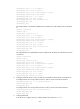
BkTunnel ID: Invalid BkInterface: N/A
The output shows that Router C communicates with network 1.1.1.0/24 through the path Router
C<—>Router D<—>Router A.
BGP FRR configuration example
Network requirements
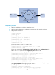
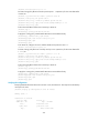
As shown in Figure 75, configure BGP FRR so that when Link B fails, BGP uses Link A to forward traffic.
Figure 75 Network diagram
Configuration procedure
1. Configure IP addresses for interfaces. (Details not shown.)
2. Configure OSPF in AS 200 to ensure connectivity among Router B, Router C, and Router D.
(Details not shown.)
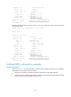
3. Configure BGP connections:
# Configure Router A to establish EBGP sessions with Router B and Router C, and advertise
network 1.1.1.1/32.
<RouterA> system-view
[RouterA] bgp 100
[RouterA-bgp] router-id 1.1.1.1
[RouterA-bgp] peer 10.1.1.2 as-number 200
[RouterA-bgp] peer 30.1.1.3 as-number 200
[RouterA-bgp] address-family ipv4 unicast
[RouterA-bgp-ipv4] peer 10.1.1.2 enable
[RouterA-bgp-ipv4] peer 30.1.1.3 enable
[RouterA-bgp-ipv4] network 1.1.1.1 32
# Configure Router B to establish an EBGP session with Router A, and an IBGP session with Router
D.
<RouterB> system-view
[RouterB] bgp 200
[RouterB-bgp] router-id 2.2.2.2
Router B
Router C
Router D
AS 200
AS 100
Router A
Loop0
1.1.1.1/32
Loop0
4.4.4.4/32
GE2/1/2
30.1.1.1/24
GE2/1/1
10.1.1.1/24
GE2/1/1
10.1.1.2/24
GE2/1/2
20.1.1.2/24
GE2/1/2
40.1.1.4/24
GE2/1/1
20.1.1.4/24
GE2/1/1
30.1.1.3/24
GE2/1/2
40.1.1.3/24
Link A
Link B
Loop0
2.2.2.2/32
Loop0
3.3.3.3/32