
R0106-HP MSR Router Series Layer 3 - IP Routing Configuration Guide(V7)


22
Summary Count : 1
Static Routing table Status : <Active>
Summary Count : 1
Destination/Mask Proto Pre Cost NextHop Interface
120.1.1.0/24 Static 65 0 10.1.1.100 GE2/1/2
Static Routing table Status : <Inactive>
Summary Count : 0
The output shows that Router A communicates with Router B through GigabitEthernet 2/1/2.
Static route FRR configuration example
Network requirements
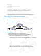
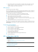
As shown in Figure 5, configure static routes on Router S, Router A, and Router D, and configure static
route FRR. When Link A becomes unidirectional, traffic can be switched to Link B immediately.
Figure 5 Network diagram
Configuration procedure
1. Configure IP addresses for interfaces. (Details not shown.)
2. Configure static route FRR on link A by using one of the following methods:
{ (Method 1.) Specify a backup next hop for static route FRR:
# Configure a static route on Router S, and specify GigabitEthernet 2/1/1 as the backup
output interface and 12.12.12.2 as the backup next hop.
<RouterS> system-view
[RouterS] ip route-static 4.4.4.4 32 gigabitethernet 2/1/2 13.13.13.2
backup-interface gigabitethernet 2/1/1 backup-nexthop 12.12.12.2
# Configure a static route on Router D, and specify GigabitEthernet 2/1/1 as the backup
output interface and 24.24.24.2 as the backup next hop.
<RouterD> system-view
[RouterD] ip route-static 1.1.1.1 32 gigabitethernet 2/1/2 13.13.13.1
backup-interface gigabitethernet 2/1/1 backup-nexthop 24.24.24.2
{ (Method 2.) Configure static route FRR to automatically select a backup next hop:
# Configure static routes on Router S, and enable static route FRR.
<RouterS> system-view
[RouterS] ip route-static 4.4.4.4 32 gigabitethernet 2/1/2 13.13.13.2