
R0106-HP MSR Router Series Layer 3 - IP Routing Configuration Guide(V7)


328
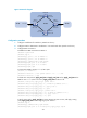
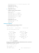
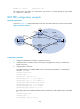
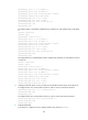
Figure 76 Network diagram
Table 14 Interface and IP address assignment
Device
Interface IP address
Device
Interface
IP address
Source N/A
10.110.1.100/2
4
Router C GE2/1/1 10.110.2.1/24
Router A GE2/1/1 10.110.1.1/24
S2/1/0 192.168.4.1/24
POS2/1/0 192.168.1.1/24
S2/1/1 192.168.2.2/24
Loop0 1.1.1.1/32
Loop0 3.3.3.3/32
Router B POS2/1/0 192.168.1.2/24 Router D S2/1/0 192.168.3.2/24
S2/1/0 192.168.2.1/24
S2/1/1 192.168.4.2/24
S2/1/1 192.168.3.1/24
Loop0 4.4.4.4/32
Loop0 2.2.2.2/32
Configuration procedure
1. Configure IP addresses for interfaces and configure OSPF for each AS to ensure intra-AS
connectivity. (Details not shown.)
2. Enable IP multicast routing, PIM-SM, and IGMP, and configure BSR boundaries:
# On Router A, enable multicast routing globally, and enable PIM-SM on interfaces.
<RouterA> system-view
[RouterA] multicast routing
[RouterA-mrib] quit
[RouterA] interface gigabitethernet 2/1/1
[RouterA-GigabitEthernet2/1/1] pim sm
[RouterA-GigabitEthernet2/1/1] quit
[RouterA] interface pos 2/1/0
[RouterA-Pos2/1/0] pim sm
[RouterA-Pos2/1/0] quit
# Configure Router B and Router D in the same way that Router A was configured.
MBGP peers
AS 100 AS 200
Source
Receiver
Router A
Router B
Router C
Router D
POS2/1/0 POS2/1/0
S2/1/1 S2/1/0
GE2/1/1
PIM-SM 1
PIM-SM 2
Loop0 Loop0
Loop0Loop0