
R0106-HP MSR Router Series Layer 3 - IP Routing Configuration Guide(V7)


364
<RouterB> system-view
[RouterB] interface serial 2/1/0
[RouterB-Serial2/1/0] ip address 1.1.2.2 24
[RouterB-Serial2/1/0] quit
# Configure a static route to subnet 10.110.0.0/24.
[RouterB] ip route-static 10.110.0.0 24 1.1.2.1
3. Configure Router C:
# Configure the IP address of the serial interface.
<RouterC> system-view
[RouterC] interface serial 2/1/1
[RouterC-Serial2/1/1] ip address 1.1.3.2 24
[RouterC-Serial2/1/1] quit
# Configure a static route to subnet 10.110.0.0/24.
[RouterC] ip route-static 10.110.0.0 24 1.1.3.1
Verifying the configuration
# Configure the IP address 10.110.0.20/24 for Host A, and specify its gateway address as 10.110.0.10.
# On Host A, Telnet to Router B that is directly connected to Router A. The operation succeeds.
# On Host A, Telnet to Router C that is directly connected to Router A. The operation fails.
# Ping Router C from Host A. The operation succeeds.
Telnet uses TCP, and ping uses ICMP. The results show the following:
• All TCP packets arriving on GigabitEthernet 2/1/1 of Router A are forwarded to the next hop
1.1. 2. 2.
• Other packets are forwarded through Serial 2/1/1.
• The interface PBR configuration is effective.
Packet length-based interface PBR configuration example
Network requirements
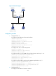
As shown in Figure 86, configure interface PBR to guide the forwarding of packets received on
GigabitEthernet 2/1/1 of Router A as follows:
• Set the next hop of packets with a length of 64 to 100 bytes to 150.1.1.2/24.
• Set the next hop of packets with a length of 101 to 1000 bytes to 151.1.1.2/24.
Router A forwards other packets according to the routing table.