
R0106-HP MSR Router Series Layer 3 - IP Routing Configuration Guide(V7)


377
Destination: 120::/64 Protocol : Static
NextHop : 10::100 Preference: 65
Interface : GE2/1/2 Cost : 0
Static Routing table Status : <Inactive>
Summary Count : 0
The output shows that Router A communicates with Router B through GigabitEthernet 2/1/2.
BFD for IPv6 static routes configuration example (indirect next
hop)
Network requirements
As shown in Figure 90:
• Router A has a route to interface Loopback 1 (2::9/128) on Router B, and the output interface is
GigabitEthernet 2/1/1.
• Router B has a route to interface Loopback 1 (1::9/128) on Router A, and the output interface is
GigabitEthernet 2/1/1.
• Router D has a route to 1::9/128, and the output interface is GigabitEthernet 2/1/1. It also has a
route to 2::9/128, and the output interface is GigabitEthernet 2/1/2.
Configure the following:
• Configure an IPv6 static route to subnet 120::/64 on Router A.
• Configure an IPv6 static route to subnet 121::/64 on Router B.
• Enable BFD for both routes.
• Configure an IPv6 static route to subnet 120::/64 and an IPv6 static route to subnet 121::/64 on
both Router C and Router D.
When the link between Router A and Router B through Router D fails, BFD can detect the failure
immediately and Router A and Router B can communicate through Router C.
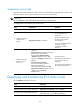
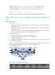
Figure 90 Network diagram
Table 18 Interface and IP address assignment
Device Interface IPv6
address
Device
Interface
IPv6 address
Router A GE2/1/1 12::1/64
Router B
GE2/1/1 11::2/64
Router A GE2/1/2 10::102/64 Router B GE2/1/2 13::1/64