
R0106-HP MSR Router Series Layer 3 - IP Routing Configuration Guide(V7)


425
The output shows that the DR is still Router D.
4. Enable DR/BDR election:
# Perform the shutdown and undo shutdown commands on each interface to enable a new DR/BD
election. (Details not shown.)
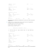
# Display neighbors on Router A. The output shows that Router C becomes the BDR.
[RouterA] display ospfv3 peer
OSPFv3 Process 1 with Router ID 1.1.1.1
Area: 0.0.0.0
-------------------------------------------------------------------------
Router ID Pri State Dead-Time InstID Interface
2.2.2.2 0 Full/DROther 00:00:36 0 GE2/1/1
3.3.3.3 2 Full/BDR 00:00:35 0 GE2/1/1
4.4.4.4 1 Full/DROther 00:00:33 0 GE2/1/1
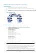
# Display neighbors on Router D.
[RouterD] display ospfv3 peer
OSPFv3 Process 1 with Router ID 4.4.4.4
Area: 0.0.0.0
-------------------------------------------------------------------------
Router ID Pri State Dead-Time InstID Interface
1.1.1.1 100 Full/DR 00:00:30 0 GE2/1/1
2.2.2.2 0 2-Way/DROther 00:00:37 0 GE2/1/1
3.3.3.3 2 Full/BDR 00:00:31 0 GE2/1/1
The output shows that Router A becomes the DR.
OSPFv3 route redistribution configuration example
Network requirements
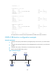
As shown in Figure 97:
• Router A, Router B, and Router C are in Area 2.
• OSPFv3 process 1 and OSPFv3 process 2 run on Router B. Router B communicates with Router A
and Router C through OSPFv3 process 1 and OSPFv3 process 2.
• Configure OSPFv3 process 2 to redistribute direct routes and the routes from OSPFv3 process 1 on
Router B, and set the default metric for redistributed routes to 3. Router C can then learn the routes
destined for 1::0/64 and 2::0/64, and Router A cannot learn the routes destined for 3::0/64 or
4::0/64.