
R0106-HP MSR Router Series Layer 3 - IP Routing Configuration Guide(V7)


430
Verifying the configuration
After all routers function correctly, perform an active/standby switchover on Router A to trigger an
OSPFv3 GR operation.
OSPFv3 NSR configuration example
Network requirements
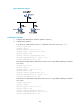
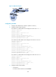
As shown in Figure 99, Router S, Router A, and Router B belong to the same AS and OSPFv3 routing
domain. Enable OSPFv3 NSR on Router S to ensure correct routing when an active/standby switchover
occurs on Router S.
Figure 99 Network diagram
Configuration procedure
1. Configure IP addresses and subnet masks for interfaces on the routers. (Details not shown.)
2. Configure OSPFv3 on the routers to make sure Router S, Router A, and Router B can communicate
with each other at Layer 3. (Details not shown.)
3. Configure OSPFv3:
# On Router A, enable OSPFv3 and set the router ID to 1.1.1.1.
<RouterA> system-view
[RouterA] ospfv3 1
[RouterA-ospfv3-1] router-id 1.1.1.1
[RouterA-ospfv3-1] quit
[RouterA] interface gigabitethernet 2/1/1
[RouterA-GigabitEthernet2/1/1] ospfv3 1 area 1
[RouterA-GigabitEthernet2/1/1] quit
# On Router B, enable OSPFv3 and set the router ID to 2.2.2.2.
<RouterB> system-view
[RouterB] ospfv3 1
[RouterB-ospfv3-1] router-id 2.2.2.2
[RouterB-ospfv3-1] quit
[RouterB] interface gigabitethernet 2/1/1
[RouterB-GigabitEthernet2/1/1] ospfv3 1 area 1
[RouterB-GigabitEthernet2/1/1] quit
# On Router S, enable OSPFv3, set the router ID to 3.3.3.3, and enable NSR.
<RouterS> system-view
[RouterS] ospfv3 1
[RouterS-ospfv3-1] router-id 3.3.3.3
[RouterS-ospfv3-1] non-stop-routing
[RouterS-ospfv3-1] quit
[RouterS] interface gigabitethernet 2/1/1
[RouterS-GigabitEthernet2/1/1] ospfv3 1 area 1