
R0106-HP MSR Router Series Layer 3 - IP Routing Configuration Guide(V7)


431
[RouterS-GigabitEthernet2/1/1] quit
[RouterS] interface gigabitethernet 2/1/2
[RouterS-GigabitEthernet2/1/2] ospfv3 1 area 1
[RouterS-GigabitEthernet2/1/2] quit
Verifying the configuration
# Verify the following:
• When an active/standby switchover occurs on Router S, the neighbor relationships and routing
information on Router A and Router B have not changed.
• The traffic from Router A to Router B has not been impacted.
BFD for OSPFv3 configuration example
Network requirements
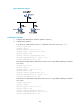
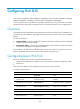
As shown in Figure 100:
• Configure OSPFv3 on Router A, Router B and Router C and configure BFD over the link Router
A<—>L2 Switch<—>Router B.
• After the link Router A<—>L2 Switch<—>Router B fails, BFD can quickly detect the failure and
notify OSPFv3 of the failure. Then Router A and Router B communicate through Router C.
Figure 100 Network diagram
Table 19 Interface and IP address assignment
Device Interface IPv6
address
Device
Interface
IPv6 address
Router A GE2/1/1 2001::1/64
Router B
GE2/1/2 2001:3::2/64
Router A GE2/1/2 2001:2::1/64 Router C GE2/1/1 2001:2::2/64
Router B GE2/1/1 2001::2/64
Router C
GE2/1/2 2001:3::1/64
Configuration procedure
1. Configure IPv6 addresses for interfaces. (Details not shown.)
2. Configure basic OSPFv3:
# Enable OSPFv3 and set the router ID to 1.1.1.1 on Router A.
<RouterA> system-view
[RouterA] ospfv3 1