
R0106-HP MSR Router Series Layer 3 - IP Routing Configuration Guide(V7)


57
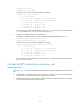
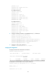
Destination: 100.1.1.0/24
Protocol: RIP Process ID: 1
SubProtID: 0x1 Age: 00h21m23s
Cost: 4 Preference: 100
Tag: 0 State: Active Adv
OrigTblID: 0x0 OrigVrf: default-vrf
TableID: 0x2 OrigAs: 0
NBRID: 0x12000003 LastAs: 0
AttrID: 0xffffffff Neighbor: 192.168.3.2
Flags: 0x1008c OrigNextHop: 192.168.3.2
Label: NULL RealNextHop: 192.168.3.2
BkLabel: NULL BkNextHop: N/A
Tunnel ID: Invalid Interface: GigabitEthernet2/1/2
BkTunnel ID: Invalid BkInterface: N/A
Configuring BFD for RIP (bidirectional control detection)
Network requirements
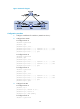
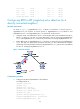
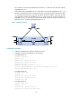
As shown in Figure 13, GigabitEthernet 2/1/2 of Router A and GigabitEthernet 2/1/1 of Router C run
RIP process 1. GigabitEthernet 2/1/1 on Router A runs RIP process 2. GigabitEthernet 2/1/2 on Router
C, and GigabitEthernet 2/1/1 and GigabitEthernet 2/1/2 on Router D run RIP process 1.
• Configure a static route destined for 100.1.1.0/24 on Router A.
• Configure a static route destined for 101.1.1.0/24 on Router C.
• Enable static route redistribution into RIP on Router A and Router C. This allows Router A to learn two
routes destined for 100.1.1.0/24 through GigabitEthernet 2/1/2 and GigabitEthernet 2/1/1. It
uses the route through GigabitEthernet 2/1/2.
• Enable BFD for RIP on GigabitEthernet 2/1/2 of Router A and GigabitEthernet 2/1/1 of Router C.
When the link over GigabitEthernet 2/1/2 fails, BFD can quickly detect the link failure and notify RIP so
RIP deletes the neighbor relationship and the route information learned on GigabitEthernet 2/1/2. It
uses the route destined for 100.1.1.0/24 through GigabitEthernet 2/1/1.
Figure 13 Network diagram
Table 6 Interface and IP address assignment
Device Interface
IP
address
Router A GigabitEthernet 2/1/1 192.168.3.1/24
Router A GigabitEthernet 2/1/2 192.168.1.1/24