
R0106-HP MSR Router Series Layer 3 - IP Services Configuration Guide(V7)

93
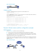
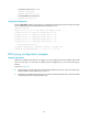
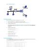
Figure 38 Network diagram
Configuration procedure
Before performing the following configuration, make sure that:
• Device A, the DNS server, and the host can reach each other.
• The IPv6 addresses of the interfaces are configured as shown in Figure 38.
1. Conf
ig
ure the DNS server:
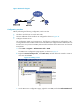
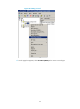
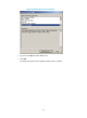
The configuration might vary by DNS server. When a PC running Windows Server 2000 acts as
the DNS server, see "Dynamic domain name resolution configuration example" for conf
iguration
information.
2. Configure the DNS proxy:
# Specify the DNS server 4.1.1.1.
<DeviceA> system-view
[DeviceA] dns server 4.1.1.1
# Enable DNS proxy.
[DeviceA] dns proxy enable
3. Configure the DNS client:
<DeviceB> system-view
# Specify the DNS server 2.1.1.2.
[DeviceB] dns server 2.1.1.2
Verifying the configuration
# Use the ping host.com command on Device B to verify the connection between the device and the host
is normal and that the translated destination IP address is 3.1.1.1.
[DeviceB] ping host.com
Ping host.com (3.1.1.1): 56 data bytes, press CTRL_C to break
56 bytes from 3.1.1.1: icmp_seq=0 ttl=255 time=1.000 ms
56 bytes from 3.1.1.1: icmp_seq=1 ttl=255 time=1.000 ms
56 bytes from 3.1.1.1: icmp_seq=2 ttl=255 time=1.000 ms
56 bytes from 3.1.1.1: icmp_seq=3 ttl=255 time=1.000 ms
56 bytes from 3.1.1.1: icmp_seq=4 ttl=255 time=2.000 ms