
R0106-HP MSR Router Series Layer 3 - IP Services Configuration Guide(V7)


113
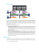
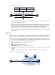
Figure 51 NAT Server operation
1. The host in the public network sends a packet destined for the public IP address and port number
of the server in the private network.
2. When the NAT device receives the packet, it matches the destination address and port number
against the NAT Server mapping. If a match is found, NAT translates the destination address and
port number in the packet to the private IP address and port number of the internal server.
3. Upon receiving a response packet from the internal server, the NAT device translates the source
private IP address and port number of the packet into the public IP address and port number of the
internal server.
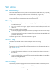
NAT444
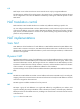
NAT444 provides carrier-grade NAT. It is a preferred solution for carriers to mitigate the IPv4 address
exhaustion. It only introduces a second layer of NAT on the carrier side, without many changes on the
customer side and the application server side. Its user logging function provides the user tracing function.
Figure 52 sh
o
ws how the NAT444 gateway works together with other devices to provide an integrated
NAT solution. The NAT444 architecture includes the following entities:
• CPE—Provides NAT services on the customer side.
• BRAS—Provides Internet access services.
• NAT444 gateway—Provides carrier-grade NAT services.
• AAA server—Cooperates with BRAS to provide user authentication, authorization, and accounting
services.
• Log server—Records user access logs and responds to queries of user access information.
Figure 52 NAT444 application diagram
192.168.1.3
192.168.1.1 20.1.1.1
20.1.1.2
NAT
Intranet
Internet
Host
Server
Dst : 20.1.1.1:8080Dst : 192.168.1.3:8080
Src : 192.168.1.3:8080
Src : 20.1.1.1:8080
Before NAT
20.1.1.1:8080
After NAT
192.168.1.3:8080
Direction
Inbound