
R0106-HP MSR Router Series Layer 3 - IP Services Configuration Guide(V7)

156
Destination IP/port: 202.38.1.1/21
DS-Lite tunnel peer: -
VPN instance/VLAN ID/VLL ID: -/-/-
Protocol: TCP(6)
Responder:
Source IP/port: 10.110.10.3/21
Destination IP/port: 202.38.1.25/53957
DS-Lite tunnel peer: -
VPN instance/VLAN ID/VLL ID: -/-/-
Protocol: TCP(6)
State: TCP_ESTABLISHED
Application: FTP
Start time: 2012-08-16 11:06:07 TTL: 26s
Interface(in) : GigabitEthernet2/1/2
Interface(out): GigabitEthernet2/1/1
Initiator->Responder: 1 packets 60 bytes
Responder->Initiator: 2 packets 120 bytes
Total sessions found: 5
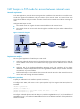
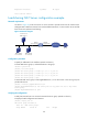
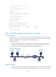
NAT with DNS mapping configuration example
Network requirements
As shown in Figure 64, the internal Web server at 10.110.10.1/16 and FTP server at 10.110.10.2/16
provide services for external user. The company has three public addresses 202.38.1.1 through
202.38.1.3. The DNS server at 202.38.1.4 is on the external network.
Configure NAT so that:
• The public IP address 202.38.1.2 is used by external users to access the Web and FTP servers.
• External users can use the public address or domain name of internal servers to access them.
• Internal users can access the internal servers by using their domain names.
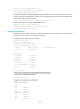
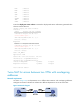
Figure 64 Network diagram
Requirements analysis
• Configure NAT Server by mapping the internal IP addresses and port numbers of the internal
servers to a public address and port numbers so that external users can access the interval servers.
FTP server
10.110.10.2/16
Host A
10.110.10.3/16
Internet
GE2/1/1
10.110.10.10/16
GE2/1/2
202.38.1.1/24
Router
Web server
10.110.10.1/16
DNS server
202.38.1.4/24
Host B
202.38.1.10/24