
R0106-HP MSR Router Series Layer 3 - IP Services Configuration Guide(V7)


286
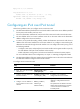
Step Command Remarks
5. Configure a destination
address for the tunnel interface.
destination ip-address
By default, no destination address is
configured for the tunnel interface.
The tunnel destination address must be
the IP address of the receiving interface
on the tunnel peer. It is used as the
destination IP address of tunneled
packets.
6. (Optional.) Set the DF bit for
tunneled packets.
tunnel dfbit enable
The DF bit is not set for tunneled packets
by default.
Configuration example
Network requirements
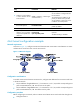
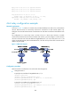
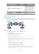
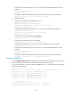
As shown in Figure 116, the two subnets Group 1 and Group 2 use private IPv4 addresses. Configure an
IPv4 over IPv4 tunnel between Router A and Router B to make the two subnets reachable to each other.
Figure 116 Network diagram
Configuration procedure
Make sure Router A and Router B can reach each other through IPv4.
• Configure Router A:
# Specify an IPv4 address for GigabitEthernet 2/1/1.
<RouterA> system-view
[RouterA] interface gigabitethernet 2/1/1
[RouterA-GigabitEthernet2/1/1] ip address 10.1.1.1 255.255.255.0
[RouterA-GigabitEthernet2/1/1] quit
# Specify an IPv4 address for Serial 2/2/0, which is the physical interface of the tunnel.
[RouterA] interface serial 2/2/0
[RouterA-Serial2/2/0] ip address 2.1.1.1 255.255.255.0
[RouterA-Serial2/2/0] quit
# Create an IPv4 over IPv4 tunnel interface tunnel 1.
[RouterA] interface tunnel 1 mode ipv4-ipv4
# Specify an IPv4 address for the tunnel interface.
[RouterA-Tunnel1] ip address 10.1.2.1 255.255.255.0
# Specify the IP address of Serial 2/2/0 as the source address for the tunnel interface.
[RouterA-Tunnel1] source 2.1.1.1