
R0106-HP MSR Router Series Layer 3 - IP Services Configuration Guide(V7)


289
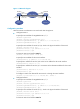
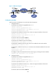
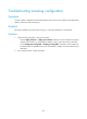
Figure 117 Network diagram
Configuration procedure
Make sure Router A and Router B can reach each other through IPv6.
• Configure Router A:
# Specify an IPv4 address for GigabitEthernet 2/1/1.
<RouterA> system-view
[RouterA] interface gigabitethernet 2/1/1
[RouterA-GigabitEthernet2/1/1] ip address 30.1.1.1 255.255.255.0
[RouterA-GigabitEthernet2/1/1] quit
# Specify an IPv6 address for Serial 2/2/0, which is the physical interface of the tunnel.
[RouterA] interface serial 2/2/0
[RouterA-Serial2/2/0] ipv6 address 2001::1:1 64
[RouterA-Serial2/2/0] quit
# Create an IPv6 tunnel interface tunnel 1.
[RouterA] interface tunnel 1 mode ipv6
# Specify an IPv4 address for the tunnel interface.
[RouterA-Tunnel1] ip address 30.1.2.1 255.255.255.0
# Specify the IP address of Serial 2/2/0 as the source address for the tunnel interface.
[RouterA-Tunnel1] source 2001::1:1
# Specify the IP address of Serial 2/2/1 on Router B as the destination address for the tunnel
interface.
[RouterA-Tunnel1] destination 2002::2:1
[RouterA-Tunnel1] quit
# Configure a static route destined for IPv4 network 2 through the tunnel interface.
[RouterA] ip route-static 30.1.3.0 255.255.255.0 tunnel 1
• Configure Router B:
# Specify an IPv4 address for GigabitEthernet 2/1/1.
<RouterB> system-view
[RouterB] interface gigabitethernet 2/1/1
[RouterB-GigabitEthernet2/1/1] ip address 30.1.3.1 255.255.255.0
[RouterB-GigabitEthernet2/1/1] quit
# Specify an IPv6 address for Serial 2/2/1, which is the physical interface of the tunnel.
[RouterB] interface serial 2/2/1
[RouterB-Serial2/2/1] ipv6 address 2002::2:1 64
[RouterB-Serial2/2/1] quit
# Create an IPv6 tunnel interface tunnel 2.
S2/2/0
2001::1:1/64
GE2/1/1
30.1.3.1/24
GE2/1/1
30.1.1.1/24
Router A
IPv6 network
IPv4
network 1
Tunnel1
30.1.2.1/24
S2/2/1
2002::2:1/64
Tunnel2
30.1.2.2/24
IPv4
network 2
Router B
IPv4 over IPv6 tunnel