
R0106-HP MSR Router Series Layer 3 - IP Services Configuration Guide(V7)


353
The output shows that Spoke 1 has established a permanent hub-spoke tunnel to Hub 1 and Hub 2.
# Ping the private address 192.168.0.4 of Spoke 2 from Spoke 1.
[Spoke2] ping 192.168.0.4
Ping 192.168.0.4 (192.168.0.4): 56 data bytes, press CTRL_C to break
56 bytes from 192.168.0.4: icmp_seq=0 ttl=255 time=4.000 ms
56 bytes from 192.168.0.4: icmp_seq=1 ttl=255 time=0.000 ms
56 bytes from 192.168.0.4: icmp_seq=2 ttl=255 time=0.000 ms
56 bytes from 192.168.0.4: icmp_seq=3 ttl=255 time=0.000 ms
56 bytes from 192.168.0.4: icmp_seq=4 ttl=255 time=1.000 ms
--- Ping statistics for 192.168.0.4 ---
5 packets transmitted, 5 packets received, 0.0% packet loss
round-trip min/avg/max/std-dev = 0.000/1.000/4.000/1.549 ms
IPv6 hub-spoke ADVPN configuration example
Network requirements
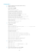
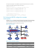
As shown in Figure 139, the primary and secondary VAM servers manage and maintain VAM client
information for all hubs and spokes. The AAA server performs authentication and accounting for VAM
clients. The two hubs back up each other, and perform data forwarding and route exchange.
Each spoke establishes a permanent ADVPN tunnel to each hub.
Figure 139 Network diagram
Table 15 Interface and IP address assignment
Device Interface IP address
Device
Interface IP address
Hub 1 GE1/0/1 1::1/64 Spoke 1 GE1/0/1 1::3/64
Tunnel1 192:168::1/64
GE1/0/2 192:168:1::1/64
Hub 2 GE1/0/1 1::2/64
Tunnel1 192:168::3/64