
R0106-HP MSR Router Series Layer 3 - IP Services Configuration Guide(V7)

390
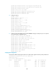
192:168:1::2 1::2 18001 S-H Success 0H 46M 8S
The output shows that Spoke 1 has established a permanent hub-spoke tunnel to Hub 1 and Hub 2.
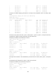
# Display the ADVPN tunnel information for Spoke 3.
[Spoke3] display advpn ipv6 session
Interface : Tunnel1
Number of sessions: 2
Private address Public address Port Type State Holding time
192:168:2::1 1::3 18001 S-H Success 0H 46M 8S
The output shows that Spoke 3 has established a permanent hub-spoke tunnel to Hub 3.
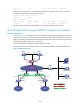
IPv4 full-mesh NAT traversal ADVPN configuration example
Network requirements
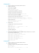
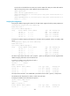
As shown in Figure 142, all the VAM servers and VAM clients reside behind a NAT gateway. The primary
and secondary VAM servers manage and maintain VAM client information for all hubs and spokes. The
AAA server performs authentication and accounting for VAM clients. The two hubs back up each other,
and perform data forwarding and route exchange.
Each spoke establishes a permanent ADVPN tunnel to each hub.
Any two spokes in the same ADVPN domain can dynamically establish a temporary ADVPN tunnel.
Figure 142 Network diagram
Spoke1 Spoke2
GE1/0/1
Site 1
Site 2
Hub1 Hub2
GE1/0/1
GE1/0/1 GE1/0/1
Tunnel1
Tunnel1
Tunnel1 Tunnel1
GE1/0/2 GE1/0/2
Primary server
Secondary server
AAA server
GE1/0/1
GE1/0/1
GE1/0/1
GE1/0/1
GE1/0/1GE1/0/1
GE1/0/2
GE1/0/2
GE1/0/2
GE1/0/2
NAT1
NAT2
NAT3
NAT4
Hub-to-Hub static tunnel
Hub-to-Spoke static tunnel
Spoke-to-Spoke dynamic tunnel
IP network