
R0106-HP MSR Router Series Layer 3 - IP Services Configuration Guide(V7)


64
Displaying and maintaining the DHCP client
Execute display command in any view.
Task Command
Display DHCP client information.
display dhcp client [ verbose ] [ interface interface-type
interface-number ]
DHCP client configuration example
Network requirements
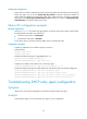
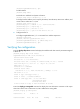
As shown in Figure 25, Router B contacts the DHCP server through GigabitEthernet 2/1/1 to obtain an
IP address, a DNS server address, and static route information. The DHCP client IP address resides on
subnet 10.1.1.0/24. The DNS server address is 20.1.1.1. The next hop of the static route to subnet
20.1.1.0/24 is 10.1.1.2.
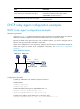
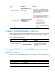
The DHCP server uses Option 121 to assign static route information to DHCP clients. Figure 24 sh
o
ws the
Option 121 format. The destination descriptor field contains the following parts: subnet mask length and
destination network address, both in hexadecimal notation. In this example, the destination descriptor is
18 14 01 01 (the subnet mask length is 24 and the network address is 20.1.1.0 in dotted decimal
notation). The next hop address is 0A 01 01 02 (10.1.1.2 in dotted decimal notation).
Figure 24 Option 121 format
Figure 25 Network diagram
Configuration procedure
1. Configure Router A:
# Specify the IP address of GigabitEthernet 2/1/1.
<RouterA> system-view
[RouterA] interface gigabitethernet 2/1/1
[RouterA-GigabitEthernet2/1/1] ip address 10.1.1.1 24
Router B
DHCP Client
DNS server
Router A
DHCP server
GE2/1/1
10.1.1.1/24
GE2/1/1
Router C
10.1.1.2/24 20.1.1.2/24
20.1.1.1/24