
R0106-HP MSR Router Series MPLS Configuration Guide(V7)


92
Collected Bandwidth : -
# Execute the display mpls lsp command or the display mpls static-cr-lsp command on each router to
display the static CRLSP information.
[RouterA] display mpls lsp
FEC Proto In/Out Label Interface/Out NHLFE
1.1.1.1/0/1 StaticCR -/20 GE2/1/1
2.1.1.2 Local -/- GE2/1/1
[RouterB] display mpls lsp
FEC Proto In/Out Label Interface/Out NHLFE
- StaticCR 20/30 GE2/1/2
3.2.1.2 Local -/- GE2/1/2
[RouterC] display mpls lsp
FEC Proto In/Out Label Interface/Out NHLFE
- StaticCR 30/- -
[RouterA] display mpls static-cr-lsp
Name LSR Type In/Out Label Out Interface State
static-cr-lsp-1 Ingress Null/20 GE2/1/1 Up
[RouterB] display mpls static-cr-lsp
Name LSR Type In/Out Label Out Interface State
static-cr-lsp-1 Transit 20/30 GE2/1/2 Up
[RouterC] display mpls static-cr-lsp
Name LSR Type In/Out Label Out Interface State
static-cr-lsp-1 Egress 30/Null - Up
# Execute the display ip routing-table command on Router A. The output shows a static route entry with
interface Tunnel 0 as the output interface. (Details not shown.)
Establishing an MPLS TE tunnel with RSVP-TE
Network requirements
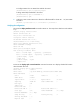
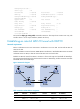
Router A, Router B, Router C, and Router D run IS-IS and all of them are Level-2 routers.
Use RSVP-TE to create an MPLS TE tunnel from Router A to Router D. The MPLS TE tunnel requires a
bandwidth of 2000 kbps.
The maximum bandwidth of each link that the tunnel traverses is 10000 kbps and the maximum
reservable bandwidth of the link is 5000 kbps.
Figure 28 Network diagram