
R0106-HP MSR Router Series MPLS Configuration Guide(V7)


98
Backup Explicit Path : -
Metric Type : TE
Record Route : Disabled Record Label : Disabled
FRR Flag : Disabled Bandwidth Protection : Disabled
Backup Bandwidth Flag: Disabled Backup Bandwidth Type: -
Backup Bandwidth : -
Bypass Tunnel : No Auto Created : No
Route Pinning : Disabled
Retry Limit : 10 Retry Interval : 2 sec
Reoptimization : Disabled Reoptimization Freq : -
Backup Type : None Backup LSP ID : -
Auto Bandwidth : Disabled Auto Bandwidth Freq : -
Min Bandwidth : - Max Bandwidth : -
Collected Bandwidth : -
# Execute the display ip routing-table command on Router A. The output shows a static route entry with
interface Tunnel 1 as the output interface. (Details not shown.)
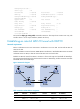
Establishing an inter-AS MPLS TE tunnel with RSVP-TE
Network requirements
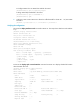
Router A and Router B are in AS 100. Router C and Router D are in AS 200. AS 100 and AS 200 use
OSPF as the IGP.
Establish an EBGP connection between ASBRs Router B and Router C. Redistribute BGP routes into OSPF
and OSPF routes into BGP, so that AS 100 and AS 200 can reach each other.
Establish an MPLS TE tunnel from Router A to Router D. The tunnel requires a bandwidth of 2000 kbps.
The maximum bandwidth of the link that the tunnel traverses is 10000 kbps, and the maximum reservable
bandwidth of the link is 5000 kbps.
Figure 29 Network diagram
Table 4 Interface and IP address assignment
Device Interface IP address
Device
Interface
IP address
Router A Loop0 1.1.1.9/32 Router C Loop0 3.3.3.9/32
GE2/1/1 10.1.1.1/24 GE2/1/1 30.1.1.1/24