
R0106-HP MSR Router Series MPLS Configuration Guide(V7)


105
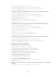
Auto Bandwidth : Disabled Auto Bandwidth Freq : -
Min Bandwidth : - Max Bandwidth : -
Collected Bandwidth : -
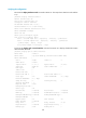
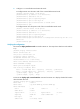
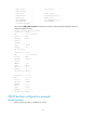
# Execute the display ip routing-table command on Router A. The output shows a static route entry with
interface Tunnel 1 as the output interface.
[RouterA] display ip routing-table
Destinations : 14 Routes : 14
Destination/Mask Proto Pre Cost NextHop Interface
1.1.1.9/32 Direct 0 0 127.0.0.1 InLoop0
2.2.2.9/32 OSPF 10 1 10.1.1.2 GE2/1/1
3.3.3.9/32 O_ASE 150 1 10.1.1.2 GE2/1/1
4.4.4.9/32 O_ASE 150 1 10.1.1.2 GE2/1/1
7.1.1.0/24 Direct 0 0 7.1.1.1 Tun1
7.1.1.1/32 Direct 0 0 127.0.0.1 InLoop0
10.1.1.0/24 Direct 0 0 10.1.1.1 GE2/1/1
10.1.1.1/32 Direct 0 0 127.0.0.1 InLoop0
20.1.1.0/24 O_ASE 150 1 10.1.1.2 GE2/1/1
30.1.1.0/24 Static 1 0 7.1.1.1 Tun1
127.0.0.0/8 Direct 0 0 127.0.0.1 InLoop0
127.0.0.1/32 Direct 0 0 127.0.0.1 InLoop0
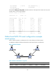
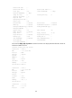
Bidirectional MPLS TE tunnel configuration example
Network requirements
Router A, Router B, Router C, and Router D all run IS-IS and they are all level-2 routers.
Use RSVP-TE to establish a bidirectional MPLS TE tunnel between Router A and Router D.
Figure 30 Network diagram
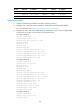
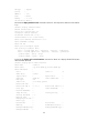
Table 5 Interface and IP address assignment
Device Interface IP address
Device
Interface
IP address
Router A Loop0 1.1.1.9/32 Router C Loop0 3.3.3.9/32
GE2/1/1 10.1.1.1/24 GE2/1/1 30.1.1.1/24