
R0106-HP MSR Router Series MPLS Configuration Guide(V7)


115
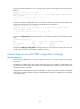
# Tracert the tunnel destination 3.3.3.9. The output shows that the used CRLSP is the one that traverses
Router B.
[RouterA] tracert –a 1.1.1.9 3.3.3.9
traceroute to 3.3.3.9 (3.3.3.9) from 1.1.1.9, 30 hops at most, 40 bytes each packet, press
CTRL_C to break
1 10.1.1.2 (10.1.1.2) 1.000 ms 1.000 ms 1.000 ms
2 * * *
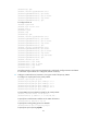
# Shut down interface GigabitEthernet 2/1/2 on Router B, and then tracert the tunnel destination. The
output shows that packets are forwarded on the CRLSP that traverses Router D.
[RouterA] tracert –a 1.1.1.9 3.3.3.9
traceroute to 3.3.3.9 (3.3.3.9) from 9.1.1.1, 30 hops at most, 40 bytes each pac
ket, press CTRL_C to break
1 30.1.1.2 (30.1.1.2) 3.000 ms 7.000 ms 3.000 ms
2 * * *
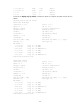
# Execute the display mpls lsp command on Router A. The output shows that only one CRLSP exists on the
router.
[RouterA] display mpls lsp
FEC Proto In/Out Label Interface/Out NHLFE
1.1.1.9/3/30107 RSVP -/1150 POS2/2/1
30.1.1.2 Local -/- POS2/2/1
# Execute the display ip routing-table command on Router A. The output shows a static route entry with
interface Tunnel 3 as the output interface. (Details not shown.)
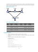
Manual bypass tunnel for FRR configuration example
Network requirements
On the primary CRLSP Router A—Router B—Router C—Router D, use FRR to protect the link Router
B—Router C.
Use RSVP-TE to establish the primary CRLSP and bypass tunnel of the MPLS TE tunnel based on the
constraints of the explicit paths. The bypass tunnel uses path Router B—Router E—Router C. Router B is
the PLR and Router C is the MP.
Configure BFD for RSVP-TE between Router B and Router C. When the link between Router B and Router
C fails, BFD can detect the failure quickly and notify RSVP-TE of the failure, so RSVP-TE can switch traffic
to the bypass tunnel.