
R0106-HP MSR Router Series MPLS Configuration Guide(V7)


121
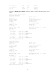
# Execute the display mpls lsp command on Router B. The output shows that the bypass tunnel is in use.
[RouterB] display mpls lsp
FEC Proto In/Out Label Interface/Out NHLFE
1.1.1.1/4/18753 RSVP 1122/3 Tun5
2.2.2.2/5/40312 RSVP -/1150 GE2/1/4
3.2.1.2 Local -/- GE2/1/4
# On the PLR, configure the interval for selecting an optimal bypass tunnel as 5 seconds.
[RouterB] mpls te
[RouterB-te] fast-reroute timer 5
[RouterB-te] quit
# On the PLR, bring up the protected interface GigabitEthernet 2/1/2.
[RouterB] interface gigabitethernet 2/1/2
[RouterB-GigabitEthernet2/1/2] undo shutdown
[RouterB-GigabitEthernet2/1/2] quit
# On Router A, execute the display interface tunnel 4 command to display information about the primary
CRLSP. The output shows that the tunnel interface is in up state. (Details not shown.)
# Wait for about 5 seconds, execute the display mpls lsp verbose command on Router B. The output
shows that Tunnel 5 is bound to interface GigabitEthernet 2/1/2 but not in use. (Details not shown.)
# Execute the display ip routing-table command on Router A. The output shows a static route entry with
interface Tunnel4 as the output interface. (Details not shown.)
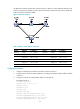
Auto FRR configuration example
Network requirements
Use RSVP-TE to set up a primary CRLSP that explicitly uses path Router A—Router B—Router C—Router D.
Configure auto FRR on Router B to automatically set up bypass tunnels for the primary CRLSP.
Configure BFD for RSVP-TE between Router B and Router C. When the link between Router B and Router
C fails, BFD can detect the failure quickly and notify RSVP-TE of the failure, so RSVP-TE can switch traffic
to the bypass tunnel.