
R0106-HP MSR Router Series MPLS Configuration Guide(V7)


122
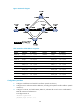
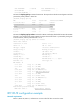
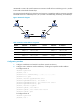
Figure 33 Network diagram
Table 8 Interface and IP address assignment
Device Interface IP address
Device
Interface
IP address
Router A Loop0 1.1.1.1/32 Router E Loop0 5.5.5.5/32
GE2/1/1 2.1.1.1/24 POS2/2/0 3.2.1.2/24
Router B Loop0 2.2.2.2/32 POS2/2/1 3.4.1.1/24
GE2/1/1 2.1.1.2/24 Router C Loop0 3.3.3.3/32
GE2/1/2 3.1.1.1/24 GE2/1/1 4.1.1.1/24
POS2/2/0 3.2.1.1/24 GE2/1/2 3.1.1.2/24
POS2/2/1 3.3.1.1/24 POS2/2/0 3.4.1.2/24
Router D Loop0 4.4.4.4/32 Router F Loop0 5.5.5.5/32
GE2/1/1 4.1.1.2/24 POS2/2/0 3.3.1.2/24
POS2/2/0 4.2.1.2/24 POS2/2/1 4.2.1.1/24
Configuration procedure
1. Configure IP addresses and masks for interfaces. (Details not shown.)
2. Configure IS-IS to advertise interface addresses, including the loopback interface address. (Details
not shown.)
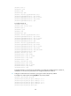
3. Configure an LSR ID, and enable MPLS, MPLS TE, and RSVP-TE on each router. Enable BFD for
RSVP-TE on Router B and Router C:
# Configure Router A.
<RouterA> system-view
[RouterA] mpls lsr-id 1.1.1.1