
R0106-HP MSR Router Series MPLS Configuration Guide(V7)


128
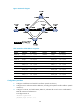
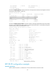
Use RSVP-TE to create a TE tunnel from Router A to Router D. Traffic of the tunnel belongs to CT 2, and the
tunnel needs a bandwidth of 4000 kbps.
The maximum bandwidth of the link that the tunnel traverses is 10000 kbps and the maximum reservable
bandwidth of the link is 10000 kbps. BC 1, BC 2, and BC 3 are 8000 kbps, 5000 kbps, and 2000 kbps.
Figure 34 Network diagram
Table 9 Interface and IP address assignment
Device Interface IP address
Device
Interface
IP address
Router A Loop0 1.1.1.9/32 Router C Loop0 3.3.3.9/32
GE2/1/1 10.1.1.1/24 GE2/1/1 30.1.1.1/24
Router B Loop0 2.2.2.9/32 POS2/2/0 20.1.1.2/24
GE2/1/1 10.1.1.2/24 Router D Loop0 4.4.4.9/32
POS2/2/0 20.1.1.1/24 GE2/1/1 30.1.1.2/24
Configuration procedure
1. Configure IP addresses and masks for interfaces. (Details not shown.)
2. Configure IS-IS to advertise interface addresses, including the loopback interface address:
# Configure Router A.
<RouterA> system-view
[RouterA] isis 1
[RouterA-isis-1] network-entity 00.0005.0000.0000.0001.00
[RouterA-isis-1] quit
[RouterA] interface gigabitethernet 2/1/1
[RouterA-GigabitEthernet2/1/1] isis enable 1
[RouterA-GigabitEthernet2/1/1] isis circuit-level level-2
[RouterA-GigabitEthernet2/1/1] quit
[RouterA] interface loopback 0
[RouterA-LoopBack0] isis enable 1
[RouterA-LoopBack0] isis circuit-level level-2
[RouterA-LoopBack0] quit
# Configure Router B.
<RouterB> system-view
[RouterB] isis 1