
R0106-HP MSR Router Series MPLS Configuration Guide(V7)


152
RSVP configuration examples
Establishing an MPLS TE tunnel with RSVP-TE
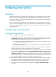
Network requirements
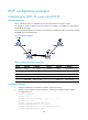
Router A, Router B, Router C, and Router D run IS-IS and all of them are Layer 2 routers.
Use RSVP-TE to create an MPLS TE tunnel from Router A to Router D. The MPLS TE tunnel requires a
bandwidth of 2000 kbps.
The maximum bandwidth of the link that the tunnel traverses is 10000 kbps and the maximum reservable
bandwidth of the link is 5000 kbps.
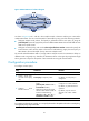
Figure 37 Network diagram
Table 10 Interface and IP address assignment
Device Interface IP address
Device
Interface
IP address
Router A Loop0 1.1.1.9/32 Router C Loop0 3.3.3.9/32
GE2/1/1 10.1.1.1/24 GE2/1/1 30.1.1.1/24
Router B Loop0 2.2.2.9/32 POS2/2/0 20.1.1.2/24
GE2/1/1 10.1.1.2/24 Router D Loop0 4.4.4.9/32
POS2/2/0 20.1.1.1/24 GE2/1/1 30.1.1.2/24
Configuration procedure
1. Configure IP addresses and masks for interfaces. (Details not shown.)
2. Configure IS-IS to advertise interface addresses, including the loopback interface address:
# Configure Router A.
<RouterA> system-view
[RouterA] isis 1
[RouterA-isis-1] network-entity 00.0005.0000.0000.0001.00
[RouterA-isis-1] quit
[RouterA] interface gigabitethernet 2/1/1
[RouterA-GigabitEthernet2/1/1] isis enable 1
[RouterA-GigabitEthernet2/1/1] isis circuit-level level-2
[RouterA-GigabitEthernet2/1/1] quit