
R0106-HP MSR Router Series MPLS Configuration Guide(V7)


228
Peer AS MsgRcvd MsgSent OutQ PrefRcv Up/Down State
3.3.3.9 100 3 6 0 0 00:00:32 Established
Verifying the configuration
# Execute the display ip routing-table vpn-instance command on the PEs.
[PE1] display ip routing-table vpn-instance vpn1
Destinations : 13 Routes : 13
Destination/Mask Proto Pre Cost NextHop Interface
0.0.0.0/32 Direct 0 0 127.0.0.1 InLoop0
10.1.1.0/24 Direct 0 0 10.1.1.2 GE2/1/1
10.1.1.0/32 Direct 0 0 10.1.1.2 GE2/1/1
10.1.1.2/32 Direct 0 0 127.0.0.1 InLoop0
10.1.1.255/32 Direct 0 0 10.1.1.2 GE2/1/1
10.3.1.0/24 BGP 255 0 3.3.3.9 POS2/1/0
127.0.0.0/8 Direct 0 0 127.0.0.1 InLoop0
127.0.0.0/32 Direct 0 0 127.0.0.1 InLoop0
127.0.0.1/32 Direct 0 0 127.0.0.1 InLoop0
127.255.255.255/32 Direct 0 0 127.0.0.1 InLoop0
224.0.0.0/4 Direct 0 0 0.0.0.0 NULL0
224.0.0.0/24 Direct 0 0 0.0.0.0 NULL0
255.255.255.255/32 Direct 0 0 127.0.0.1 InLoop0
The output shows that PE 1 has a route to the remote CE. Output on PE 2 is similar.
# Verify that CEs of the same VPN can ping each other, whereas those of different VPNs cannot. For
example, CE 1 can ping CE 3 (10.3.1.1), but it cannot ping CE 4 (10.4.1.1). (Details not shown.)
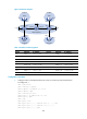
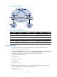
Configuring MPLS L3VPN over a GRE tunnel
Network requirements
CE 1 and CE 2 belong to VPN 1. The PEs support MPLS. The P router does not support MPLS and provides
only IP functions.
On the backbone, use a GRE tunnel to encapsulate and forward VPN packets to implement MPLS
L3VPN.
Configure tunnel policies on the PEs, and specify the tunnel type for VPN traffic as GRE.