
R0106-HP MSR Router Series MPLS Configuration Guide(V7)
232
[PE1-bgp-vpnv4] quit
[PE1-bgp] quit
# Configure PE 2 in the same way that PE 1 is configured. (Details not shown.)
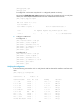
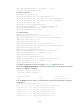
# Execute the display bgp peer vpnv4 command on the PEs. This example uses PE 1 to verify that
a BGP peer relationship in Established state has been established between the PEs.
[PE1] display bgp peer vpnv4
BGP local router ID: 1.1.1.9
Local AS number: 100
Total number of peers: 1 Peers in established state: 1
Peer AS MsgRcvd MsgSent OutQ PrefRcv Up/Down State
2.2.2.9 100 5 7 0 2 00:00:43 Established
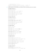
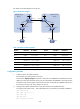
6. Configure a GRE tunnel:
# Configure PE 1.
[PE1] interface tunnel 0 mode gre
[PE1-Tunnel0] source loopback 0
[PE1-Tunnel0] destination 2.2.2.9
[PE1-Tunnel0] ip address 20.1.1.1 24
[PE1-Tunnel0] mpls enable
[PE1-Tunnel0] quit
# Configure PE 2.
[PE2] interface tunnel 0 mode gre
[PE2-Tunnel0] source loopback 0
[PE2-Tunnel0] destination 1.1.1.9
[PE2-Tunnel0] ip address 20.1.1.2 24
[PE2-Tunnel0] mpls enable
[PE2-Tunnel0] quit
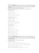
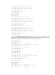
Verifying the configuration
# Use the following command on CE 1 to verify that the CEs has learned the interface route from each
other.
[CE1] display ip routing-table
Destinations : 13 Routes : 13
Destination/Mask Proto Pre Cost NextHop Interface
0.0.0.0/32 Direct 0 0 127.0.0.1 InLoop0
10.1.1.0/24 Direct 0 0 10.1.1.1 GE2/1/1
10.1.1.0/32 Direct 0 0 10.1.1.1 GE2/1/1
10.1.1.1/32 Direct 0 0 127.0.0.1 InLoop0
10.1.1.255/32 Direct 0 0 10.1.1.1 GE2/1/1
10.2.1.0/24 BGP 255 0 10.1.1.2 GE2/1/1
127.0.0.0/8 Direct 0 0 127.0.0.1 InLoop0
127.0.0.0/32 Direct 0 0 127.0.0.1 InLoop0
127.0.0.1/32 Direct 0 0 127.0.0.1 InLoop0
127.255.255.255/32 Direct 0 0 127.0.0.1 InLoop0