
R0106-HP MSR Router Series MPLS Configuration Guide(V7)

240
Run OSPF on the MPLS backbone of each AS.
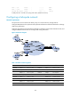
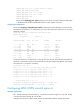
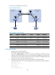
Figure 66 Network diagram
Table 15 Interface and IP assignment
Device Interface IP address
Device
Interface IP address
CE 1 GE2/1/1 10.1.1.1/24 CE 2 GE2/1/1 10.2.1.1/24
PE 1 Loop0 1.1.1.9/32 PE 2 Loop0 4.4.4.9/32
GE2/1/1 10.1.1.2/24 GE2/1/1 10.2.1.2/24
POS2/1/0 172.1.1.2/24 POS2/1/0 162.1.1.2/24
ASBR-PE1 Loop0 2.2.2.9/32 ASBR-PE2 Loop0 3.3.3.9/32
POS2/1/0 172.1.1.1/24 POS2/1/0 162.1.1.1/24
POS2/1/1 192.1.1.1/24 POS2/1/1 192.1.1.2/24
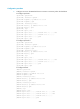
Configuration procedure
1. Configure IGP on the MPLS backbone.
This example uses OSPF. (Details not shown.)
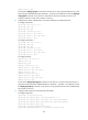
# Execute the display ospf peer command to verify that each ASBR-PE has established an OSPF
adjacency in Full state with the PE in the same AS, and that PEs and ASBR-PEs in the same AS have
learned the routes to the loopback interfaces of each other. Verify that each ASBR-PE and the PE in
the same AS can ping each other. (Details not shown.)
2. Configure basic MPLS and MPLS LDP on the MPLS backbone to establish LDP LSPs:
# Configure basic MPLS on PE 1, and enable MPLS LDP on the interface connected to ASBR-PE 1.
<PE1> system-view
[PE1] mpls lsr-id 1.1.1.9
[PE1] mpls ldp
[PE1-ldp] quit
[PE1] interface pos 2/1/0
Loop0 Loop0
Loop0 Loop0
POS2/1/1 POS2/1/1
POS2/1/0
POS2/1/0
POS2/1/0
POS2/1/0
GE2/1/1
GE2/1/1
GE2/1/1
GE2/1/1
CE 1 CE 2
AS 65001 AS 65002
PE 1
PE 2
ASBR-PE 2
ASBR-PE 1
MPLS backbone
MPLS backbone
AS 100
AS 200