
R0106-HP MSR Router Series MPLS Configuration Guide(V7)


256
[PE2-bgp-vpn1] address-family ipv4 unicast
[PE2-bgp-ipv4-vpn1] peer 20.0.0.2 enable
[PE2-bgp-ipv4-vpn1] quit
[PE2-bgp-vpn1] quit
[PE2-bgp] quit
6. Configure CE 2:
# Configure an IP address for GigabitEthernet 2/1/1.
<CE2> system-view
[CE2] interface gigabitethernet 2/1/1
[CE2-GigabitEthernet2/1/1] ip address 20.0.0.2 24
[CE2-GigabitEthernet2/1/1] quit
# Establish an EBGP peer relationship with PE 2, and redistribute VPN routes.
[CE2] bgp 65002
[CE2-bgp] peer 20.0.0.1 as-number 600
[CE2-bgp] address-family ipv4 unicast
[CE2-bgp-ipv4] peer 20.0.0.1 enable
[CE2-bgp-ipv4] import-route direct
[CE2-bgp-ipv4] quit
[CE2-bgp] quit
Verifying the configuration
# Execute the display ip routing table command on CE 1 and CE 2 to verify that CE 1 and CE 2 have
a route to each other. Verify that CE 1 and CE 2 can ping each other. (Details not shown.)
Configuring MPLS L3VPN carrier's carrier
Network requirements
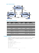
Configure carrier's carrier for the scenario shown in Figure 69. In this scenario:
• PE 1 and PE 2 are the provider carrier's PE routers. They provide VPN services for the customer
carrier.
• CE 1 and CE 2 are the customer carrier's routers. They are connected to the provider carrier's
backbone as CE routers.
• PE 3 and PE 4 are the customer carrier's PE routers. They provide MPLS L3VPN services for the end
customers.
• CE 3 and CE 4 are customers of the customer carrier.
The key to carrier's carrier deployment is to configure exchange of two kinds of routes:
• Exchange of the customer carrier's internal routes on the provider carrier's backbone.
• Exchange of the end customers' VPN routes between PE 3 and PE 4, the PEs of the customer carrier.
In this process, an MP-IBGP peer relationship must be established between PE 3 and PE 4.