
R0106-HP MSR Router Series MPLS Configuration Guide(V7)


264
b. Adds the export target attribute of the MPLS VPN on the service provider network to the
extended community attribute list.
c. Forwards the VPNv4 route.
• To implement exchange of sub-VPN routes between customer PEs and service provider PEs,
MP-EBGP peers must be established between provider PEs and provider CEs.
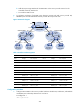
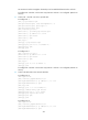
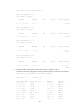
Figure 70 Network diagram
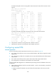
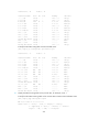
Table 19 Interface and IP assignment
Device Interface IP address
Device
Interface
IP address
CE 1 Loop0 2.2.2.9/32 CE 2 Loop0 5.5.5.9/32
POS2/1/0 10.1.1.2/24 POS2/1/0 21.1.1.2/24
POS2/1/1 11.1.1.1/24 POS2/1/1 20.1.1.1/24
CE 3 GE2/1/1 100.1.1.1/24 CE 4 GE2/1/1 120.1.1.1/24
CE 5 GE2/1/1 110.1.1.1/24 CE 6 GE2/1/1 130.1.1.1/24
PE 1 Loop0 3.3.3.9/32 PE 2 Loop0 4.4.4.9/32
POS2/1/0 11.1.1.2/24 POS2/1/0 30.1.1.2/24
POS2/1/1 30.1.1.1/24 POS2/1/1 21.1.1.1/24
PE 3 Loop0 1.1.1.9/32 PE 4 Loop0 6.6.6.9/32
GE2/1/1 100.1.1.2/24 GE2/1/1 120.1.1.2/24
GE2/1/2 110.1.1.2/24 GE2/1/2 130.1.1.2/24
POS2/1/1 10.1.1.1/24 POS2/1/1 20.1.1.2/24
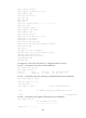
Configuration procedure
1. Configure MPLS L3VPN on the service provider backbone. Enable IS-IS, enable LDP, and establish
an MP-IBGP peer relationship between PE 1 and PE 2:
# Configure PE 1.
<PE1> system-view
PE 1
CE 3
AS 65410
SUB_VPN 1
PE 2
Customer VPN
PE 3
CE 6
AS 65421
SUB_VPN 2
PE 4
POS2/1/1
POS2/1/0
Carrier VPN
Customer VPN
POS2/1/0
POS2/1/1
POS2/1/1
POS2/1/0
Loop0
Lo
op0
CE 1 CE 2
L
oo
p0
Loo
p0
Loo
p0
POS2/1/0
POS2/1/1
GE2/1/1
GE2/1/1 GE2/1/1
GE2/1/2
POS2/1/1
POS2/1/1
AS 100
AS 200
VPN 1
AS 200
VPN 1
CE 5
AS 65411
SUB_VPN 2
GE2/1/1
GE2/1/2
CE 4
AS 65420
SUB_VPN 1
GE2/1/1
GE2/1/1