
R0106-HP MSR Router Series MPLS Configuration Guide(V7)


273
Configuring HoVPN
Network requirements
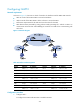
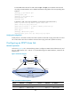
As shown in Figure 71, there are two levels of networks: the backbone and the MPLS VPN networks.
• SPEs act as PEs to allow MPLS VPNs to access the backbone.
• UPEs act as PEs of the MPLS VPNs to allow end users to access the VPNs.
• Performance requirements for the UPEs are lower than those for the SPEs.
• SPEs advertise routes permitted by routing policies to UPEs, permitting CE 1 and CE 3 in VPN 1 to
communicate with each other and forbidding CE 2 and CE 4 in VPN 2 from communicating with
each other.
Figure 71 Network diagram
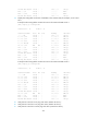
Table 20 Interface and IP assignment
Device Interface IP address
Device
Interface
IP address
CE 1 GE2/1/1 10.2.1.1/24 CE 3 GE2/1/1 10.1.1.1/24
CE 2 GE2/1/1 10.4.1.1/24 CE 4 GE2/1/1 10.3.1.1/24
UPE 1 Loop0 1.1.1.9/32 UPE 2 Loop0 4.4.4.9/32
GE2/1/1 10.2.1.2/24 GE2/1/1 172.2.1.1/24
GE2/1/2 10.4.1.2/24 GE2/1/2 10.1.1.2/24
GE2/1/3 172.1.1.1/24 GE2/1/3 10.3.1.2/24
SPE 1 Loop0 2.2.2.9/32 SPE 2 Loop0 3.3.3.9/32
GE2/1/1 172.1.1.2/24 GE2/1/1 180.1.1.2/24
GE2/1/2 180.1.1.1/24 GE2/1/2 172.2.1.2/24
Configuration procedure
1. Configure UPE 1:
# Configure basic MPLS and MPLS LDP to establish LDP LSPs.