
R0106-HP MSR Router Series MPLS Configuration Guide(V7)


280
# Create BGP-VPN instances for VPN instances vpn1 and vpn2, so the VPNv4 routes learned
according to the RT attributes can be added into the BGP routing tables of the corresponding VPN
instances.
[SPE2-bgp] ip vpn-instance vpn1
[SPE2-bgp-vpn1] quit
[SPE2-bgp] ip vpn-instance vpn2
[SPE2-bgp-vpn2] quit
[SPE2-bgp] quit
# Advertise to UPE 2 the routes permitted by a routing policy (the routes of CE 1).
[SPE2] ip prefix-list hope index 10 permit 10.2.1.1 24
[SPE2] route-policy hope permit node 0
[SPE2-route-policy-hope-0] if-match ip address prefix-list hope
[SPE2-route-policy-hope-0] quit
[SPE2] bgp 100
[SPE2-bgp] address-family vpnv4
[SPE2-bgp-vpnv4] peer 4.4.4.9 upe route-policy hope export
Verifying the configuration
# Verify that CE 1 and CE3 can learn each other's interface routes and can ping each other. CE 2 and
CE 4 cannot learn each other's interface routes and cannot ping each other. (Details not shown.)
Configuring an OSPF sham link
Network requirements
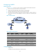
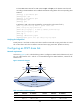
As shown in Figure 72, CE 1 and CE 2 belong to VPN 1. Configure an OSPF sham link between PE 1 and
PE 2 so traffic between CE 1 and CE 2 is forwarded through the MPLS backbone, instead of the
backdoor link.
Figure 72 Network diagram
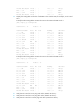
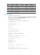
Table 21 Interface and IP assignment
Device Interface IP address
Device
Interface
IP address
CE 1 GE2/1/1 100.1.1.1/24 CE 2 GE2/1/1 120.1.1.1/24
S2/1/1 20.1.1.1/24 S2/1/1 30.1.1.2/24
S2/1/1
Loop0
Loop0
S2/1/0
Sham-link
GE2/1/1
CE 1 Router A CE 2
PE 2PE 1
GE2/1/1
S2/1/1 S2/1/1 S2/1/0 S2/1/1
Loop1 Loop1
GE2/1/1
GE2/1/1
OSPF Area 1
Backdoor link