
R0106-HP MSR Router Series MPLS Configuration Guide(V7)
284
[PE2-ospf-100-area-0.0.0.1] quit
[PE2-ospf-100] quit
Verifying the configuration
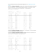
# Execute the display ip routing-table vpn-instance command again on the PEs to verify the following
results: (Details not shown.)
• The path to the peer CE is now along the BGP route across the backbone.
• A route to the sham link destination address exists.
# Execute the display ip routing-table command on the CEs. The output shows that the next hop of the
OSPF route to the peer CE is the Ethernet interface connected to the PE. This means that VPN traffic to the
peer is forwarded over the backbone. (Details not shown.)
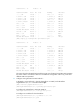
# Verify that a sham link has been established on PEs, for example, on PE 1.
[PE1] display ospf sham-link
OSPF Process 100 with Router ID 100.1.1.2
Sham link
Area Neighbor ID Source IP Destination IP State Cost
0.0.0.1 120.1.1.2 3.3.3.3 5.5.5.5 P-2-P 10
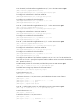
# Verify that the peer state is Full on PE 1.
[PE1] display ospf sham-link area 1
OSPF Process 100 with Router ID 100.1.1.2
Sham-Link: 3.3.3.3 --> 5.5.5.5
Neighbor ID: 120.1.1.2 State: Full
Area: 0.0.0.1
Cost: 10 State: P-2-P Type: Sham
Timers: Hello 10s, Dead 40s, Retransmit 5s, Transmit Delay 1s
Request list: 0 Retransmit list: 0
Configuring MCE
Network requirements
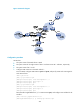
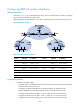
As shown in Figure 73, VPN 2 runs RIP. Configure the MCE device to separate routes from different VPNs
and to advertise the VPN routes to PE 1 through OSPF.