
R0106-HP MSR Router Series MPLS Configuration Guide(V7)


294
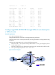
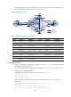
CE 1 and CE 2 reside in the same site. CE1, CE2, and CE 3 all use AS number 600.
• To avoid route loss, configure BGP AS number substitution on PEs.
• To avoid routing loops, configure the same SoO attribute on PE 1 and PE 2 for CE 1 and CE 2.
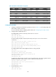
Figure 75 Network diagram
Table 23 Interface and IP assignment
Device Interface IP address
Device
Interface IP address
CE 1 Loop0 100.1.1.1/32 CE 3 Loop0 200.1.1.1 /32
GE2/1/1 10.1.1.1/24 GE2/1/1 10.3.1.1/24
CE 2 GE2/1/1 10.2.1.1/24 PE 2 Loop0 2.2.2.9/32
PE 1 Loop0 1.1.1.9/32 GE2/1/1 10.2.1.2/24
GE2/1/1 10.1.1.2/24 GE2/1/2 40.1.1.1/24
GE2/1/2 20.1.1.1/24 GE2/1/3 20.1.1.2/24
GE2/1/3 30.1.1.1/24 P Loop0 3.3.3.9/32
PE 3 Loop0 4.4.4.9/32 GE2/1/1 30.1.1.2/24
GE2/1/1 10.3.1.2/24 GE2/1/2 40.1.1.2/24
GE2/1/2 50.1.1.2/24 GE2/1/3 50.1.1.1/24
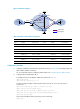
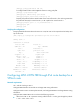
Configuration procedure
1. Configure basic MPLS L3VPN:
{ Configure OSPF on the MPLS backbone to allow the PEs and P device to learn the routes of the
loopback interfaces from each other.
{ Configure basic MPLS and MPLS LDP on the MPLS backbone to establish LDP LSPs.
{ Establish MP-IBGP peer relationship between the PEs to advertise VPN IPv4 routes.
{ Configure the VPN instance of VPN 1 on PE 1 to allow CE 1 to access the network.
{ Configure the VPN instance of VPN 1 on PE 2 to allow CE 2 to access the network.
Loop0
Loop0
Loop0
PE 1
P
PE 3
CE 2
CE 3
VPN 1
AS 600
VPN 1
AS 600
GE2/1/2
GE2/1/2
GE2/1/3
GE2/1/1
GE2/1/1
GE2/1/1
GE2/1/1
GE2/1/1
MPLS backbone
AS 100
CE 1
GE2/1/1
GE2/1/1
Loop0
GE2/1/2
GE2/1/3
GE2/1/3
GE2/1/2
PE 2
Loop0
Loop0