
R0106-HP MSR Router Series MPLS Configuration Guide(V7)


296
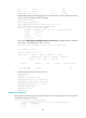
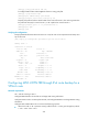
Destinations : 14 Routes : 14
Destination/Mask Proto Pre Cost NextHop Interface
0.0.0.0/32 Direct 0 0 127.0.0.1 InLoop0
10.2.1.0/24 Direct 0 0 10.2.1.1 GE2/1/1
10.2.1.0/32 Direct 0 0 10.2.1.1 GE2/1/1
10.2.1.1/32 Direct 0 0 127.0.0.1 Inloop0
10.2.1.255/32 Direct 0 0 10.2.1.1 GE2/1/1
10.3.1.0/24 BGP 255 0 10.2.1.2 GE2/1/1
127.0.0.0/8 Direct 0 0 127.0.0.1 InLoop0
127.0.0.0/32 Direct 0 0 127.0.0.1 InLoop0
127.0.0.1/32 Direct 0 0 127.0.0.1 InLoop0
127.255.255.255/32 Direct 0 0 127.0.0.1 InLoop0
200.1.1.1/32 BGP 255 0 10.2.1.2 GE2/1/1
224.0.0.0/4 Direct 0 0 0.0.0.0 NULL0
224.0.0.0/24 Direct 0 0 0.0.0.0 NULL0
255.255.255.255/32 Direct 0 0 127.0.0.1 InLoop0
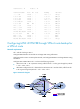
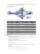
Configuring MPLS L3VPN FRR through VPNv4 route backup for
a VPNv4 route
Network requirements
CE 1 and CE 2 belong to VPN 1.
Configure EBGP between CEs and PEs to exchange VPN routing information.
Configure OSPF to ensure connectivity between PEs, and configure MP-IBGP to exchange VPNv4 routing
information.
Configure MPLS L3VPN FRR on PE 1 to achieve the following purposes:
• When the link PE 1—PE 2 operates correctly, traffic from CE 1 to CE 2 goes through the path CE
1—PE 1—PE 2—CE 2.
• When BFD configured on PE 1 detects that the LSP between PE 1 and PE 2 fails, traffic from CE 1
to CE 2 goes through the path CE 1—PE 1—PE 3—CE 2.
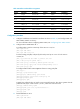
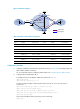
Figure 76 Network diagram