
R0106-HP MSR Router Series MPLS Configuration Guide(V7)


298
Verifying the configuration
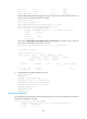
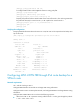
# Display detailed information about the route to 4.4.4.4/32 on PE 1. The output shows the backup next
hop for the route.
[PE1] display ip routing-table vpn-instance vpn1 4.4.4.4 32 verbose
Summary Count : 1
Destination: 4.4.4.4/32
Protocol: BGP Process ID: 0
SubProtID: 0x1 Age: 00h00m03s
Cost: 0 Preference: 255
IpPre: N/A QosLocalID: N/A
Tag: 0 State: Active Adv
OrigTblID: 0x0 OrigVrf: default-vrf
TableID: 0x102 OrigAs: 300
NibID: 0x15000002 LastAs: 300
AttrID: 0x2 Neighbor: 2.2.2.2
Flags: 0x110060 OrigNextHop: 2.2.2.2
Label: 1146 RealNextHop: 172.1.1.2
BkLabel: 1275 BkNextHop: 172.2.1.3
Tunnel ID: Invalid Interface: GE2/1/2
BkTunnel ID: Invalid BkInterface: GE2/1/3
FtnIndex: 0x0
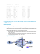
Configuring MPLS L3VPN FRR through VPNv4 route backup for
an IPv4 route
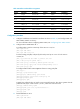
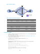
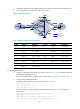
Network requirements
CE 1 and CE 2 belong to VPN 1.
Configure EBGP between CEs and PEs to exchange VPN routing information.
Configure OSPF to ensure connectivity between PEs, and configure MP-IBGP to exchange VPNv4 routing
information.
Configure MPLS L3VPN FRR on PE 2 to achieve the following purposes:
• When the link PE 2—CE 2 operates correctly, traffic from CE 1 to CE 2 goes through the path CE
1—PE 1—PE 2—CE 2.
• When BFD configured on PE 2 detects that the link between PE 2 and CE 2 fails, traffic from CE 1
to CE 2 goes through the path CE 1—PE 1—PE 2—PE 3—CE 2.