
R0106-HP MSR Router Series MPLS Configuration Guide(V7)


299
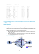
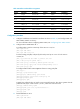
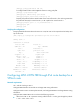
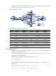
Figure 77 Network diagram
Table 25 Interface and IP address assignment
Device Interface IP
address
Device
Interface
IP address
CE 1 Loop0 5.5.5.5/32 PE 2 Loop0 2.2.2.2/32
GE2/1/1 10.2.1.1/24
GE2/1/1 172.1.1.2/24
PE 1 Loop0 1.1.1.1/32
GE2/1/2 10.1.1.2/24
GE2/1/1 10.2.1.2/24
GE2/1/3 172.3.1.2/24
GE2/1/2 172.1.1.1/24 PE 3 Loop0 3.3.3.3/32
GE2/1/3 172.2.1.1/24
GE2/1/1 172.2.1.3/24
CE 2 Loop0 4.4.4.4/32
GE2/1/2 10.3.1.2/24
GE2/1/1 10.1.1.1/24
GE2/1/3 172.3.1.3/24
GE2/1/2 10.3.1.1/24
Configuration procedure
1. Configure IP addresses and masks for interfaces as shown in Table 25, and configure BGP and
MPLS L3VPN. (Details not shown.)
For more information about configuring MPLS L3VPN, see "Configuring basic MPLS L3VPN."
2. Config
ure MPLS L3VPN FRR on PE 2:
# Configure the source IP address of BFD echo packets as 12.1.1.1.
<PE2> system-view
[PE2] bfd echo-source-ip 12.1.1.1
# Create routing policy frr, and specify the backup next hop as 3.3.3.3 for the route to
4.4.4.4/32.
[PE2] ip prefix-list abc index 10 permit 4.4.4.4 32
[PE2] route-policy frr permit node 10
[PE2-route-policy] if-match ip address prefix-list abc
[PE2-route-policy] apply fast-reroute backup-nexthop 3.3.3.3
[PE2-route-policy] quit
# Use echo-mode BFD to detect the primary route connectivity.
[PE2] bgp 100
CE 2
CE 1
VPN 1
VPN 1
MPLS
backbone
PE 2
PE 1
PE 3
GE2/1/1
GE2/1/2
GE2/1/2GE2/1/1
GE2/1/2
GE2/1/1
GE2/1/2
GE2/1/3
GE2/1/1
GE2/1/1
Loop0
Loop0
Loop0
Loop0
GE2/1/3
GE2/1/3
Loop0
Primary link
Backup link