
R0106-HP MSR Router Series MPLS Configuration Guide(V7)


301
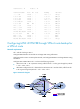
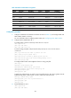
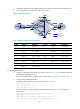
• When BFD configured on PE 2 detects that the link between PE 2 and PE 3 fails, traffic from CE 1
to CE 2 goes through the path CE 1—PE 1—PE 2—CE 2.
Figure 78 Network diagram
Table 26 Interface and IP address assignment
Device Interface IP
address
Device
Interface
IP address
CE 1 Loop0 5.5.5.5/32 PE 2 Loop0 2.2.2.2/32
GE2/1/1 10.2.1.1/24
GE2/1/1 172.1.1.2/24
PE 1 Loop0 1.1.1.1/32
GE2/1/2 10.1.1.2/24
GE2/1/1 10.2.1.2/24
GE2/1/3 172.3.1.2/24
GE2/1/2 172.1.1.1/24 PE 3 Loop0 3.3.3.3/32
GE2/1/3 172.2.1.1/24
GE2/1/1 172.2.1.3/24
CE 2 Loop0 4.4.4.4/32
GE2/1/2 10.3.1.2/24
GE2/1/1 10.1.1.1/24
GE2/1/3 172.3.1.3/24
GE2/1/2 10.3.1.1/24
Configuration procedure
1. Configure IP addresses and masks for interfaces as shown in Table 26, and configure BGP and
MPLS L3VPN. (Details not shown.)
For more information about configuring MPLS L3VPN, see "Configuring basic MPLS L3VPN."
2. Config
ure MPLS L3VPN FRR on PE 2:
# Configure BFD to test the connectivity of the LSP to 3.3.3.3/32.
<PE2> system-view
[PE2] mpls bfd enable
[PE2] mpls bfd 3.3.3.3 32
# Create routing policy frr, and specify the backup next hop as 10.1.1.1 for the route to
4.4.4.4/32.
[PE2] ip prefix-list abc index 10 permit 4.4.4.4 32
[PE2] route-policy frr permit node 10
[PE2-route-policy] if-match ip address prefix-list abc
[PE2-route-policy] apply fast-reroute backup-nexthop 10.1.1.1