
R0106-HP MSR Router Series MPLS Configuration Guide(V7)


329
[PE2-LoopBack0] quit
[PE2] interface pos 2/1/0
[PE2-Pos2/1/0] ip address 172.2.1.2 24
[PE2-Pos2/1/0] quit
[PE2] ospf
[PE2-ospf-1] area 0
[PE2-ospf-1-area-0.0.0.0] network 172.2.1.0 0.0.0.255
[PE2-ospf-1-area-0.0.0.0] network 3.3.3.9 0.0.0.0
[PE2-ospf-1-area-0.0.0.0] quit
[PE2-ospf-1] quit
# On PE 1, verify that the PEs have learned the routes to the loopback interfaces of each other.
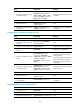
[PE1] display ip routing-table protocol ospf
Summary Count : 5
OSPF Routing table Status : <Active>
Summary Count : 3
Destination/Mask Proto Pre Cost NextHop Interface
2.2.2.9/32 OSPF 10 1 172.1.1.2 POS2/1/0
3.3.3.9/32 OSPF 10 2 172.1.1.2 POS2/1/0
172.2.1.0/24 OSPF 10 2 172.1.1.2 POS2/1/0
OSPF Routing table Status : <Inactive>
Summary Count : 2
Destination/Mask Proto Pre Cost NextHop Interface
1.1.1.9/32 OSPF 10 0 1.1.1.9 Loop0
172.1.1.0/24 OSPF 10 1 172.1.1.1 POS2/1/0
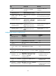
# On PE 1, verify that OSPF adjacencies in Full state have been established between PE 1, P, and
PE 2.
[PE1] display ospf peer verbose
OSPF Process 1 with Router ID 1.1.1.9
Neighbors
Area 0.0.0.0 interface 172.1.1.1(POS2/1/0)'s neighbors
Router ID: 2.2.2.9 Address: 172.1.1.2 GR State: Normal
State: Full Mode: Nbr is Master Priority: 1
DR: 172.1.1.2 BDR: 172.1.1.1 MTU: 0
Options is 0x02 (-|-|-|-|-|-|E|-)
Dead timer due in 39 sec
Neighbor is up for 00:00:29
Authentication Sequence: [ 0 ]
Neighbor state change count: 6
2. Configure basic MPLS and enable MPLS LDP on the MPLS backbone to establish LDP LSPs:
# Configure PE 1.
[PE1] mpls lsr-id 1.1.1.9