
R0106-HP MSR Router Series MPLS Configuration Guide(V7)


334
Destination: 2001:2::/96 Protocol : Direct
NextHop : :: Preference: 0
Interface : GE2/1/2 Cost : 0
Destination: 2001:2::2/128 Protocol : Direct
NextHop : ::1 Preference: 0
Interface : InLoop0 Cost : 0
Destination: 2001:4::/96 Protocol : BGP4+
NextHop : ::FFFF:3.3.3.9 Preference: 255
Interface : POS2/1/0 Cost : 0
Destination: FE80::/10 Protocol : Direct
NextHop : :: Preference: 0
Interface : NULL0 Cost : 0
Destination: FF00::/8 Protocol : Direct
NextHop : :: Preference: 0
Interface : NULL0 Cost : 0
The output shows that PE 1 has routes to the remote CEs. Output on PE 2 is similar.
# Verify that CEs of the same VPN can ping each other, whereas those of different VPNs should not. For
example, CE 1 can ping CE 3 (2001:3::1), but cannot ping CE 4 (2001:4::1). (Details not shown.)
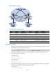
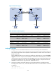
Configuring an IPv6 MPLS L3VPN over a GRE tunnel
Network requirements
CE 1 and CE 2 belong to VPN 1. The PEs support MPLS, while the P router does not support MPLS and
provides only IP functions.
On the backbone, use a GRE tunnel to encapsulate and forward packets for IPv6 MPLS L3VPN.
Configure tunnel policies on the PEs, and specify the tunnel type for VPN traffic as GRE.