
R0106-HP MSR Router Series MPLS Configuration Guide(V7)


339
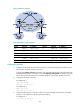
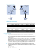
Figure 83 Network diagram
Table 29 Interface and IP assignment
Device Interface IP address
Device
Interface IP address
CE 1 GE2/1/1 2001:1::1/96 CE 2 GE2/1/1 2001:2::1/96
PE 1 Loop0 1.1.1.9/32 PE 2 Loop0 4.4.4.9/32
GE2/1/1 2001:1::2/96 GE2/1/1 2001:2::2/96
POS2/1/0 172.1.1.2/24 POS2/1/0 162.1.1.2/24
ASBR-PE1 Loop0 2.2.2.9/32 ASBR-PE2 Loop0 3.3.3.9/32
POS2/1/0 172.1.1.1/24 POS2/1/0 162.1.1.1/24
POS2/1/1 2002:1::1/96 POS2/1/1 2002:1::2/96
Configuration procedure
1. Configure an IGP on each MPLS backbone to ensure IP connectivity within the backbone.
This example uses OSPF. Be sure to advertise the route to the 32-bit loopback interface address of
each router through OSPF. Use the loopback interface address of a router as the router's LSR ID.
(Details not shown.)
# Each ASBR-PE and the PE in the same AS can establish an OSPF adjacency. Execute the display
ospf peer command to verify that each ASBR-PE has established an OSPF adjacency in Full state
with the PE in the same AS, and that the PEs and ASBR-PEs in the same AS have learned the routes
to the loopback interfaces of each other. Execute the ping command to verify that the PEs and
ASBR-PEs in the same AS can ping each other. (Details not shown.)
2. Configure basic MPLS and enable MPLS LDP on each MPLS backbone to establish LDP LSPs:
# Configure basic MPLS on PE 1, and enable MPLS LDP for both PE 1 and the interface connected
to ASBR-PE 1.
<PE1> system-view
[PE1] mpls lsr-id 1.1.1.9
Loop0 Loop0
Loop0 Loop0
POS2/1/1 POS2/1/1
POS2/1/0
POS2/1/0
POS2/1/0
POS2/1/0
GE2/1/1
GE2/1/1
GE2/1/1
GE2/1/1
CE 1 CE 2
AS 65001 AS 65002
PE 1
PE 2
ASBR-PE 2
ASBR-PE 1
MPLS backbone
MPLS backbone
AS 100
AS 200