
R0106-HP MSR Router Series MPLS Configuration Guide(V7)


364
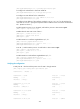
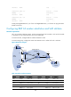
Figure 87 Network diagram
Table 32 Interface and IP assignment
Device Interface IP address
Device
Interface
IP address
CE 1 GE2/1/1 10:1::2/96 P Loop0 2.2.2.9/32
GE2/1/2 100::1/96 GE2/1/1 20.1.1.2/24
PE 1 Loop0 10.1.1.1/32 GE2/1/2 30.1.1.1/24
GE2/1/1 10:1::1/96 PE 2 Loop0 10.1.1.2/32
GE2/1/2 20.1.1.1/24 GE2/1/1 10:2::1/96
CE 2 GE2/1/1 10:2::2/96 GE2/1/2 30.1.1.2/24
GE2/1/2 200::1/96
Configuration procedure
1. Configuring basic IPv6 MPLS L3VPN:
{ Configure OSPF on the MPLS backbone to allow the PEs and P device to learn the routes of the
loopback interfaces from each other.
{ Configure basic MPLS and MPLS LDP on the MPLS backbone to establish LDP LSPs.
{ Establish an MP-IBGP peer relationship between the PEs to advertise VPN IPv6 routes.
{ Configure the VPN instance of VPN 1 on PE 1 to allow CE 1 to access the network.
{ Configure the VPN instance of VPN 1 on PE 2 to allow CE 2 to access the network.
{ Configure BGP as the PE-CE routing protocol, and redistribute routes of the CEs into the PEs.
For more information about basic IPv6 MPLS L3VPN configurations, see "Configuring IPv6 MPLS
L3VPNs."
# Execute the display ipv6 r
outing-table command on CE 2 to verify that CE 2 has not learned the
route to the VPN (100::/96) behind CE 1.
<CE2> display ipv6 routing-table
Destinations : 6 Routes : 6