
R0106-HP MSR Router Series MPLS Configuration Guide(V7)


368
Interface : NULL0 Cost : 0
Destination: FE80::/10 Protocol : Direct
NextHop : :: Preference: 0
Interface : NULL0 Cost : 0
Destination: FF00::/8 Protocol : Direct
NextHop : :: Preference: 0
Interface : NULL0 Cost : 0
# Verify that GigabitEthernet 2/1/2 of CE 1 and GigabitEthernet 2/1/2 of CE 2 can ping each other.
(Details not shown.)
Configuring BGP AS number substitution and SoO attribute
Network requirements
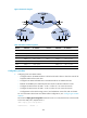
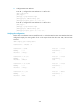
CE 1, CE 2, and CE 3 belong to VPN 1, and are connected to PE1, PE 2, and PE 3. CE 1 and CE 2 reside
in the same site. CE1, CE2, and CE 3 all use AS number 600.
To avoid route loss, configure BGP AS number substitution on PEs.
To avoid routing loops, configure the same SoO attribute on PE 1 and PE 2 for CE 1 and CE 2.
Figure 88 Network diagram
Table 33 Interface and IP assignment
Device Interface IP address
Device
Interface
IP address
CE 1 Loop0 100::1/96 CE 3 Loop0 200::1/96
GE2/1/1 10:1::1/96 GE2/1/1 10:3::1/96
CE 2 GE2/1/1 10:2::1/96 PE 2 Loop0 2.2.2.9/32
PE 1 Loop0 1.1.1.9/32 GE2/1/1 10:2::2/96
GE2/1/1 10:1::2/96 GE2/1/2 40.1.1.1/24
Loop0
Loop0
Loop0
PE 1
P
PE 3
CE 2
CE 3
VPN 1
AS 600
VPN 1
AS 600
GE2/1/2
GE2/1/2
GE2/1/3
GE2/1/1
GE2/1/1
GE2/1/1
GE2/1/1
GE2/1/1
MPLS backbone
AS 100
CE 1
GE2/1/1
GE2/1/1
Loop0
GE2/1/2
GE2/1/3
GE2/1/3
GE2/1/2
PE 2
Loop0
Loop0