
R0106-HP MSR Router Series MPLS Configuration Guide(V7)


374
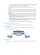
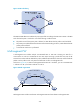
3. Set up an AC between a PE and a CE:
Set up an AC by configuring a link layer connection (such as a PPP connection) between a PE and
a CE.
An AC can be one of the following types:
{ Layer 3 physical interface—Transparently forwards received packets over the bound PW. The
Layer 3 physical interface can be an Ethernet interface, or an ATM interface.
{ Layer 3 subinterface—Forwards packets received from the corresponding link (VLAN, ATM
VPC, ATM VCC, or FR DLCI ) to the bound PW. In this mode, VLANs are unique on a per
interface basis rather than on a global basis.
{ VLAN interface—Forwards packets received from the VLAN to the bound PW. In this mode,
VLANs are globally unique.
NOTE:
W
hen VLANs are
g
lobally unique, packets with the same VLAN ID are forwarded over the PW bound
w
ith that VLAN ID re
g
ardless of the receivin
g
interfaces. If VLANs are unique on a per interface basis,
packets with the same VLAN ID from different interfaces can be forwarded over different PWs.
4. Bind the AC to the PW:
Bind the Layer 3 physical interface, Layer 3 subinterface, or VLAN interface to the PW, so the PE
forwards packets between the AC and the PW.
Local connection establishment
To set up a local MPLS L2VPN connection between two CEs:
1. Set up ACs:
Configure the link layer protocol to set up an AC between the PE and each CE. For more
information, see "Set up an AC between a PE and a CE:."
2. Bind the two ACs:
Bind the PE's interfaces
connected to the two CEs so the PE can forward packets between CEs.
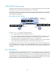
PW types
MPLS L2VPN transports Layer 2 data of different data link layer protocols through PWs. A PE
encapsulates a Layer 2 packet received from an AC according to the PW type. The PW type is
determined by the AC type, as shown in Table 34.
Table 34 Relationship betw
een
AC types and PW types
AC type PW type
Ethernet
Ethernet
VLAN
PPP PPP
HDLC HDLC