
R0106-HP MSR Router Series MPLS Configuration Guide(V7)


394
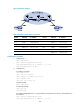
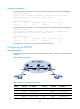
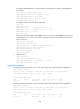
Figure 99 Network diagram
Table 35 Interface and IP address assignment
Device Interface IP address
Device
Interface
IP address
CE 1 GE2/1/1 100.1.1.1/24 P Loop0 192.4.4.4/32
PE 1 Loop0 192.2.2.2/32 GE2/1/1 10.1.1.2/24
GE2/1/1 - GE2/1/2 10.2.2.2/24
GE2/1/2 10.1.1.1/24 PE 2 Loop0 192.3.3.3/32
CE 2 GE2/1/1 100.1.1.2/24 GE2/1/1 -
GE2/1/2 10.2.2.1/24
Configuration procedure
1. Configure CE 1.
<CE1> system-view
[CE1] interface gigabitethernet 2/1/1
[CE1-GigabitEthernet2/1/1] ip address 100.1.1.1 24
[CE1-GigabitEthernet2/1/1] quit
2. Configure PE 1:
# Configure an LSR ID.
<PE1> system-view
[PE1] interface loopback 0
[PE1-LoopBack0] ip address 192.2.2.2 32
[PE1-LoopBack0] quit
[PE1] mpls lsr-id 192.2.2.2
# Enable L2VPN.
[PE1] l2vpn enable
# Enable global LDP.
[PE1] mpls ldp
[PE1-ldp] quit
# Configure GigabitEthernet 2/1/2 (the interface connected to the P device), and enable LDP on
the interface.
[PE1] interface gigabitethernet 2/1/2
[PE1-GigabitEthernet2/1/2] ip address 10.1.1.1 24