
R0106-HP MSR Router Series MPLS Configuration Guide(V7)


401
# Verify that CE 1 and CE 2 can ping each other. (Details not shown.)
Configuring IP interworking over an LDP PW
Network requirements
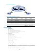
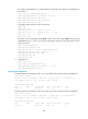
CE 1 and PE 1 are connected through Ethernet interfaces. CE 2 and PE 2 are connected through serial
interfaces, and they use PPP as the link layer protocol.
Configure an LDP PW between PE 1 and PE 2 and enable interworking on PEs so GigabitEthernet 2/1/1
on CE 1 can communicate with Serial 2/1/0 on CE 2.
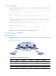
Figure 101 Network diagram
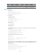
Table 37 Interface and IP address assignment
Device Interface IP address
Device
Interface
IP address
CE 1 GE2/1/1 100.1.1.1/24 P Loop0 192.4.4.4/32
PE 1 Loop0 192.2.2.2/32 GE2/1/1 10.1.1.2/24
GE2/1/1 - GE2/1/2 10.2.2.2/24
GE2/1/2 10.1.1.1/24 PE 2 Loop0 192.3.3.3/32
CE 2 S2/1/0 100.1.1.2/24 S2/1/0 -
GE2/1/1 10.2.2.1/24
Configuration procedure
1. Configure CE 1.
<CE1> system-view
[CE1] interface gigabitethernet 2/1/1
[CE1-GigabitEthernet2/1/1] ip address 100.1.1.1 24
[CE1-GigabitEthernet2/1/1] quit
2. Configure PE 1:
# Configure an LSR ID.
<PE1> system-view
[PE1] interface loopback 0
[PE1-LoopBack0] ip address 192.2.2.2 32
[PE1-LoopBack0] quit