
R0106-HP MSR Router Series MPLS Configuration Guide(V7)


412
# Display L2VPN PW information on PE 2. The output shows that a remote CCC connection has been
established.
[PE2] display l2vpn pw
Flags: M - main, B - backup, H - hub link, S - spoke link, N - no split horizon
Total number of PWs: 1, 1 up, 0 blocked, 0 down, 0 defect
Xconnect-group Name: ccc
Peer PW ID/Rmt Site In/Out Label Proto Flag Link ID State
10.2.2.2 - 202/102 Static M 0 Up
# Verify that CE 1 and CE 2 can ping each other. (Details not shown.)
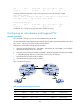
Configuring an intra-domain multi-segment PW
Network requirements
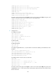
As shown in Figure 104, there is no public tunnel between PE 1 and PE 2. There is an MPLS TE tunnel
between PE 1 and P, and an MPLS TE tunnel between P and PE 2.
Configure a multi-segment PW between PE 1 and PE 2, so CE 1 and CE 2 can communicate over the
backbone. The multi-segment PW includes an LDP PW between PE 1 and P, and a static PW between P
and PE 2. The two PWs are concatenated on P.
Figure 104 Network diagram
Table 40 Interface and IP address assignment
Device Interface IP address
Device
Interface
IP address
CE 1 GE2/1/1 100.1.1.1/24 P Loop0 192.4.4.4/32
PE 1 Loop0 192.2.2.2/32 GE2/1/1 23.1.1.2/24
GE2/1/2 23.1.1.1/24 GE2/1/2 26.2.2.2/24
CE 2 GE2/1/1 100.1.1.2/24 PE 2 Loop0 192.3.3.3/32
GE2/1/2 26.2.2.1/24
Configuration procedure
1. Configure CE 1.
<CE1> system-view
[CE1] interface gigabitethernet 2/1/1