
R0106-HP MSR Router Series MPLS Configuration Guide(V7)


439
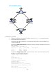
Figure 107 Network diagram
Configuration procedure
1. Configure IP addresses and masks for interfaces as shown in Figure 107. (Details not shown.)
2. Create MPLS TE tunnels on Router A:
# Create two MPLS TE tunnels (Tunnel 1 and Tunnel 2) to Router D. For more information, see
"Configuring MPLS TE."
# Execute the display mpls tunnel all command on Router A to display information about the two
MPLS TE tunnels.
<RouterA> display mpls tunnel all
Destination Type Tunnel/NHLFE VPN Instance
4.4.4.4 CRLSP Tunnel1 -
4.4.4.4 CRLSP Tunnel2 -
# Execute the display interface tunnel command on Router A. The output shows that the tunnel
interface is up. This example uses Tunnel 1.
<RouterA> display interface tunnel 1
Tunnel1
Current state: UP
Line protocol state: UP
Description: Tunnel1 Interface
Bandwidth: 64kbps
Maximum Transmit Unit: 1496
Internet Address is 10.1.10.1/24 Primary
Tunnel source unknown, destination 4.4.4.4
Tunnel TTL 255
Tunnel protocol/transport CR_LSP